Colour gradient editor
Colour gradients offer an easy way to define stunning colour schemes for contour plotting. The idea behind the colour gradients is that we just define a few waypoints representing certain colours then the colours between the waypoints are automatically generated with a given interpolation method and resolution.
Enable gradient shading
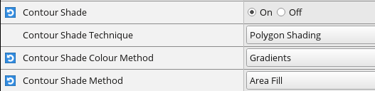
To enable the colour gradient mode in the Contouring icon we need to use contour shading and set the Contour Shade Colour Method to “Gradients”. This is how it looks in the Contouring icon editor:
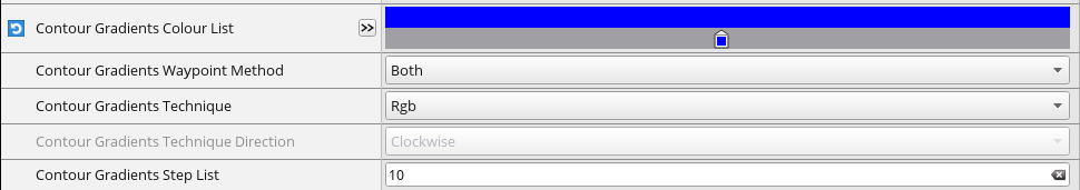
Having set this we need to scroll further down in the icon editor to find the gradient settings. This is what we can see by default:
Start editing
To edit Contour Gradients Colour List open its helper by clicking on the << button:
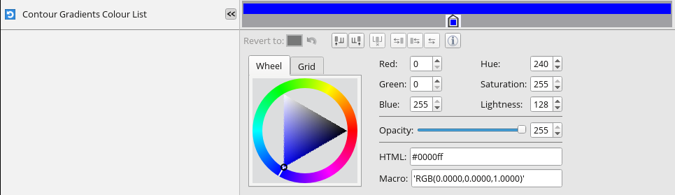
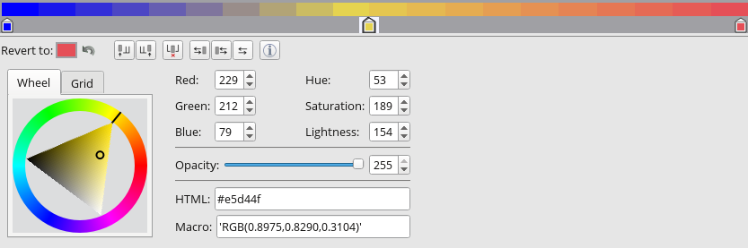
By default the gradient list only contains one waypoint. Using the

button we can add a new waypoint to the right of the current one and change its colour (e.g. to red) using the colour wheel:
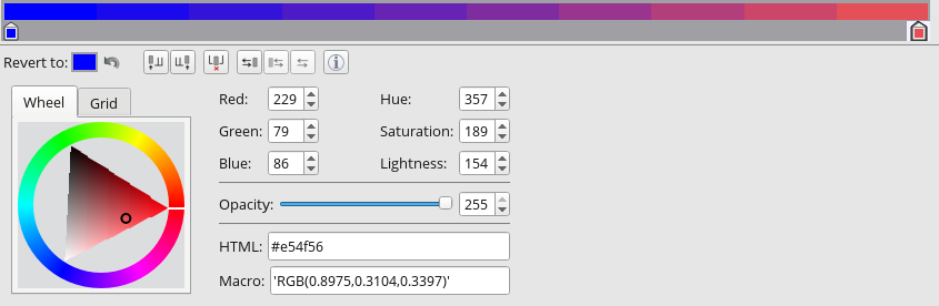
With the current settings the gradient was generated by linear interpolation in the RGB colour space (see Colour Gradients Technique) with 10 steps between the two waypoints (see Colour Gradients Steps List).
Note
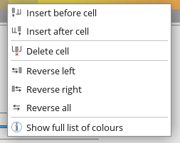
This is the full list of actions implemented for the colour gradient editor (“cell” here means waypoint):
Gradient techniques
There are other gradient techniques available on top of the RGB-base one (this is the default). These are as follows:
HCL: the interpolation is done in the Hue-Chroma-Lightness colour space
HSL: the interpolation is done in the Hue-Saturation-Lightness colour space
Both in the HCL and HSL spaces we can choose an interpolation direction along the colour wheel (hue values). The can be done by setting using Contour Gradients Technique Direction either to clockwise or anticlockwise.
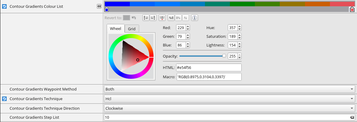
This is how our gradient would look by setting the technique to “HCL” and the direction to “clockwise”:
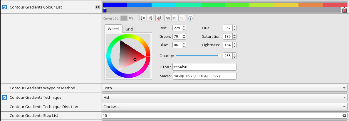
and this is how with the “HSL” technique and “clockwise” direction:
Waypoint methods
So far we have only had two waypoints. If we add a new waypoint in the middle and sets its colour (e.g. to yellow) we will see something like this (with the “RGB” technique):
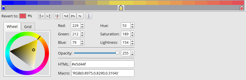
Note that the colour of the waypoint in the middle is used both in the left and right gradient segment. This happens because we set Colour Gradient Waypoint Method to “both”. The other options are as follows:
ignore: the waypoint colour is omitted from both segments
left: the waypoint colour is only used in the left segment
right. the waypoint colour is only used in right segment
E.g. by setting this option to “left” we would generate this gradient:
Changing the resolution
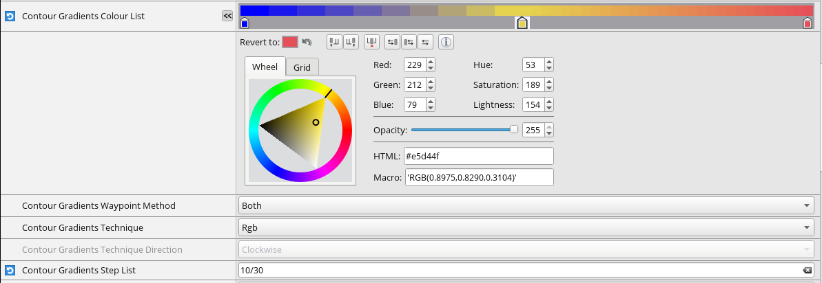
The gradient resolution can be set for each segment independently by using a list for Colour Gradients Steps List. E.g. by setting it to “10/30” we can generate something like this where the second segment is almost continuous:
Warning
Please use the Colour Gradients Steps List with extra care because although smooth gradients look great but the memory and time needed to generate the plot can increase significantly.
Mapping the waypoints to contour values
The gradient editor is only dealing with waypoints and is decoupled from the actual values the waypoints are mapped to. The first waypoint is simply mapped to the first contour value, the second waypoint is to the second value and so on.